quasivoid
W8BH LC meter
A seemingly well known and well liked LC meter design came from AADE, Almost All Digital Electronics, but the man who ran the business died in 2015 (before my time as an electronics hobbyist), and AADE died with him. The AADE LC meter seems to be impossible to find second hand.
Thankfully, the details of the design were well publicized, and as I understand it it was actually available as a kit. As such, there are a number of designs based on it, particularly the core circuit which actually performs the measurement.
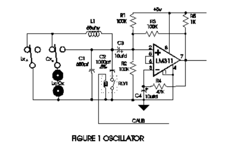
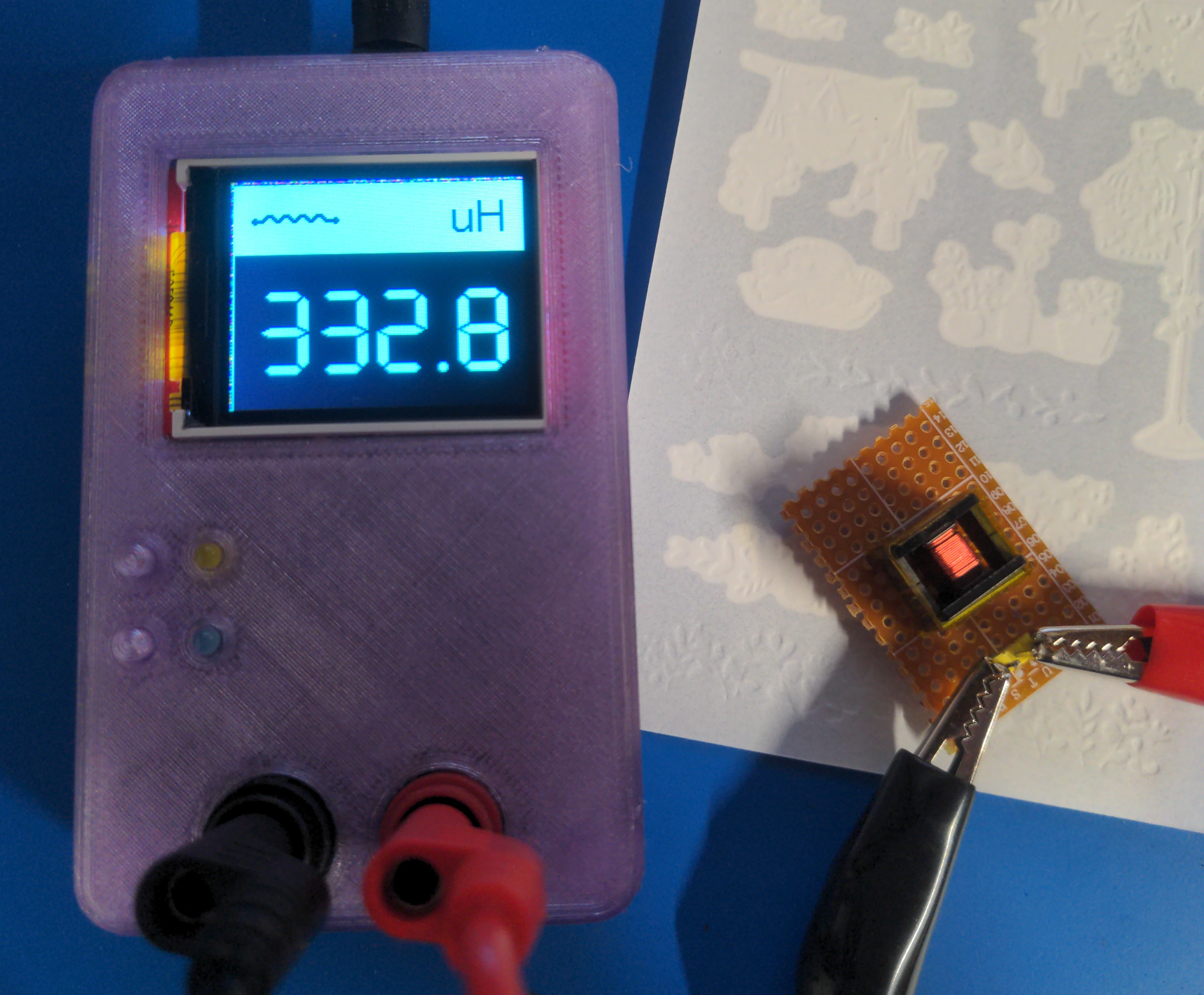
Essentially, a relaxation oscillator formed from an LM311 comparator creatures a square wave whose edges cause ringing in an LC tank formed by a known inductor and unknown capacitor or known capacitor and unknown inductor. The ringing of the tank then causes the comparator to produce a square wave whose frequency is equal to the frequency of the ringing, the resonant frequency of the LC tank. Its a very clever circuit! There is much more information about it in this document, as well as information about the original kit.
The known capacitor is selected within a tight value tolerance. The inductors value does not need to be selected as tightly, since it may be calibrated against the known capacitor.
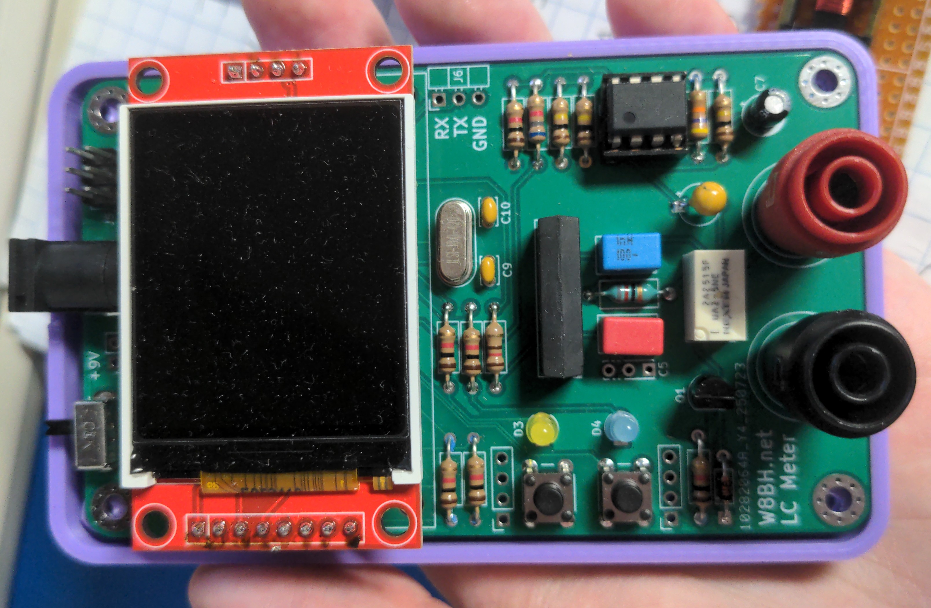
As previously stated, there are a number of designs based on this circuit. Of them, W8BH’s design caught my interest. It is very well documented, I like the design, and I like that it utilizes an AVR microcontroller rather than a PIC.
I ordered the PCB for it from JLCPCB, which only cost me $6 after shipping. The complete BOM, including extras like sockets and battery clips for the enclosure, from DigiKey came out to around $30. Finding the correct LCD module was the trickiest part, I managed to get it from AliExpress for $2.53. Searching “ST7735” yielded the best results for me.
Here is a DigiKey list which includes everything to build the LC meter. Everything listed on the BOM, appropriate sockets, and extras which are recommended for use when utilizing the enclosure with a 9V battery compartment.
During assembly, I tried out using blue tack to hold components in place as I flipped the board over. This worked great! I could have sworn that I took some pictures, but evidently I did not. You have to strategize so that no blue tack gets stuck in nooks it can’t be removed but other than that it worked great.
I’m pretty stoked about how it turned out. Unfortunately, I struggled to get the battery compartment to print right. The cover wouldn’t fit, and its clip would easily break, so I opted to print the version without the compartment. I always have 9V batteries floating around my desk anyways, including a bunch of “rechargable” ones, so this works out fine. Plus, as I create more of my own gizmos and gadgets, I can design them without battery compartments so that they are powered by the 9Vs which are always in circulation.